Welcome back! You can find Part 1 here.
When I left off, the chassis had been gussied-up and the transformers were re-painted. Before I reassembled it all back together I thought that having the bare-chassis, free from the all weight added by the transformers, would be the best time to electrically refurbish the amp. Charles Hansen ran some excellent articles about completely-redoing a 222C in AudioXpress, and Craig Ostby of NOS Valves was always willing to lend his knowledge.
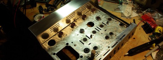
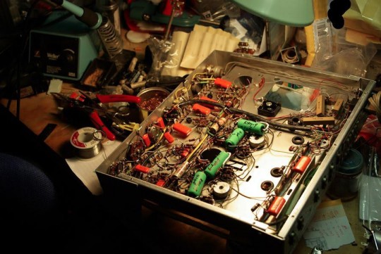
And here it is! All I have to do is test everything…
… But first I need to line up the tools of the trade!
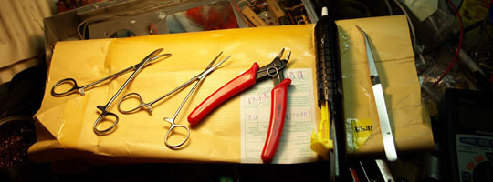
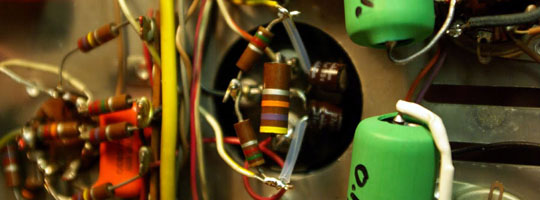
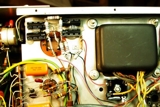
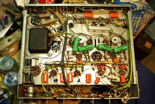
What do we have here? Two different styles of hemostats, flush cutters, a solder sucking tool, and some normally-closed tweezers. A soldering iron is always a plus. In addition to these tools a good multimeter is also very useful, you’ll need one for testing the resistors. I went whole-hog and replaced all the capacitors because at this age, why not.
For the power supply capacitors I went with JJ parts, for the exception of one can which I couldn’t order in the configuration I required, and I added the missing section underneath using Nichicon parts. Everything outside of the power supply is Vishay/Sprague ‘Orange Drops,’ with the coupling capacitors being replaced with 0.1µF 1kV K40y-9 parts–1kV wasn’t chosen for any reason, other than being bought in a large quantity to bring the price right down.
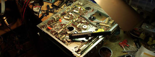
As I went along, unwrapping the point-to-point connections, checking resistors and replacing parts, I’d find a few components that were just terrible to get at–buried under crisscrossing wires or other resistors. It’s in these situations where the hemostats came in handy, snaking the old parts out and shuffling the new parts in. This took a long night to wrap up.
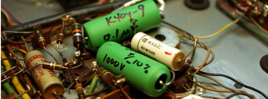
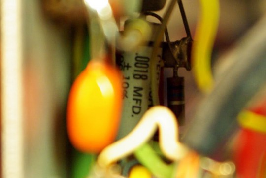
Phew! Hey, check it out–I had to extend the leads on the K40y-9 parts, and took a photo to show the size comparison. The body was insulated with heatshrink to prevent any shorting against the metal body.
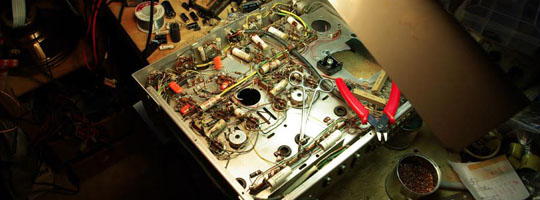
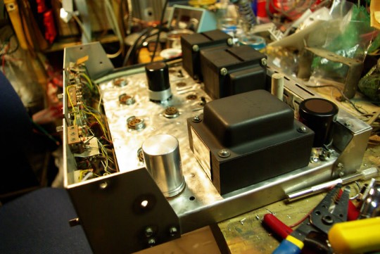
After I swapped out all those caps I wired up the transformers and flipped it back over for another photo.
The next issue that I had to address was the selenium rectifier. They’re old and they fail with age, however popping that out and installing a new silicon rectifier isn’t as straight forward as one might think. The old rectifier dropped more voltage over it than the a silicon rectifier might, and this has to be taken into consideration. There’s an excellent article on the topic that can be found here.
My rule-of-thumb is to size the resistor to drop about 10 volts, simulating the drop of the old selenium rectifier. If the equipment requires 50 milliamperes, we can use Ohm’s Law to
calculate:R = V(drop) / I(DC) = 10 V / 0.050 A = 200 ohms
This is only a rule-of-thumb. If you want to duplicate the exact original output voltage, start with a resistor of about 100 ohms and measure the output voltage with the equipment operating. Adjust the resistor value up or down until you achieve the voltage specified by the manufacturer of the equipment. Typical values will be from 20 to 200 ohms. The resistor has to dissipate some power, which means it will generate heat, so be sure to use a resistor rated for the power. In the example above, the approximate power required will be:
P = V^2 / R = 10^2 / 200 = 0.5 watts
Don’t use a half-watt resistor! A half-watt resistor gets very hot when dissipating a half-watt. I would recommend at least 100% to 200% safety factor. In fact, 5 watt resistors are probably easier to find than 2 watt types. If your current calculation is different, use a resistor rated for at least twice the power calculated. Resistors are cheap, so don’t cut corners.
And this is the result–it’s a bit of a hack at this point because I didn’t have the right resistors nor the correct wattage part on-hand, but it worked! Note that this is a negative-supply, and so the positive terminal from the rectifier goes to ground. Now, the bias supply also powers the 12.6V heaters of the four 12AX7 tubes in the preamp, as a series string. At 12.6V the heaters draw 150 mA of current, which in series is 50.4V at 150 mA; I chose to run the string at 48V as a matter of personal preference. I followed the above procedure assuming an original drop of 10V over the selenium rectifier, but found that subbing in a 68 ohm resistor (10V_drop / 0.150 A, rounded to nearest standard value) dropped the output voltage to lower than what I desired, thus leading to a bit of a hack job as shown in the photo. The caps are 100µF/100V parts and each resistors are 20 ohms/2W, and more importantly the desired output of 48V.
The old bias capacitor was left in place, its leads were clipped, and hot glue holds the new pieces in place.
Wrestling with the amp, I found this:
Awww… it was buried in the faceplate, but’s in the tone control circuit so: it sees little voltage, it sees little use, and thus I justified it to myself to forget about it.
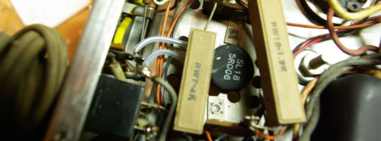
The final part I had to install was a thermistor. A thermistor is a resistor whose resistance varies based on its temperature. The purpose of the thermistor it to limit te inrush current to the amp–saves the tube heaters and is easier on the transformers and other parts. I bought a bunch of SL18 parts (an NTC thermistor) at a good price and used it simply because I had it. Its cold resistance is 2.5 ohms, which goes to 0.06 ohms at the rated current, has a rated current of 8A, and a time constant of 100 seconds. I’m using it nowhere near 8A so I’m safe with that limit. The way that this device works is that the power is applied, it flows through the thermistor into the transformer, and this flow of current causes the thermistor to heat up (The Scott 222C has a 1.2A SLO-BLO fuse, so if I assume 1.2A of current through the 2.5 ohm thermistor, the thermistor starts to dissipate 3.6W as heat), but because of the NTC properties of this part, as it heats up the resistance drops, effectively making itself of negligible resistance.
So what I see when I turn my amp on is a nice, ~minute long warm-up of my amp. Ahh, component longevity.
And now I was ready for my first test of the bias supply. I hooked up my isolation transformer and my VARIAC to the amplifier, adding a meter to measure the current draw and a meter to measure the bias supply.
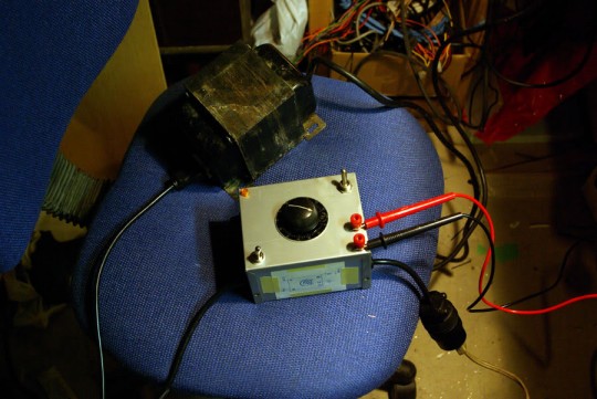
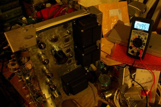
Socketed a set of Sovtek 12AX7 beater tubes I have and I measured 49.5V, a little bit more than the expected 48V, but still in range for what the heaters can handle. After this step I used the amp a little, biasing up some near-pairs of tubes that I had, and it worked!
Here’s a parting image for Part 2–I swapped in a cement power resistor into the bias supply–and stay tuned for Part 3, where I hack things up!
One comment
Pingback: pperivolarisThe Scott 222C Restoration, Part 3 - pperivolaris