Welcome back! You can find Part 2 here and Part 1 here.
At this point I decided to load all the tubes up and run a voltage test, verifying the operation of the power supply and the circuit as a whole. Now, the original circuit requires two pairs of matched tubes (ideally a matched quad). I have a modified Eico 667 tube tester which has a set of tip jacks added to it that allow me to measure cathode current while the tube is under test (I’ll give that its own post in the future), and I managed to pluck out two pairs that were close~ish.
I unfortunately have no photos from this testing session, but it sounded… off. Some quick measurements and I was able to get the tubes balanced before running out the potentiometer. Still, I was at the extreme for the bias adjustment and I knew that (a) I wanted to run old-stock tubes without paying $hundreds for them, and (b) new 7189 tubes are expensive!
I put on my robe and wizard hat.
Taking a step back, I last wrapped up part 2 with this photo:
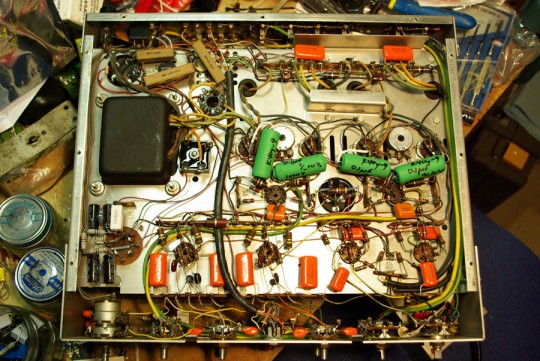
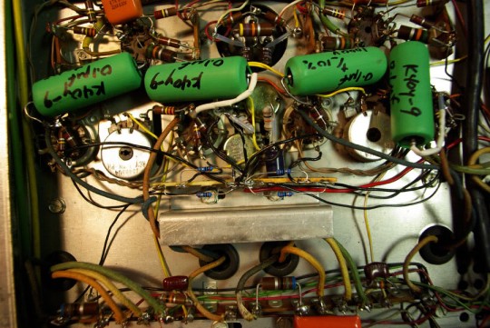
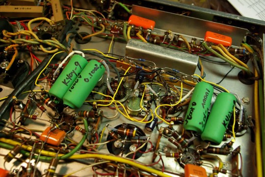
As the caption states, this is an overview of the work done to get the amplifier restored to a functionally stock-state. Here is a photo of the reworked circuit:
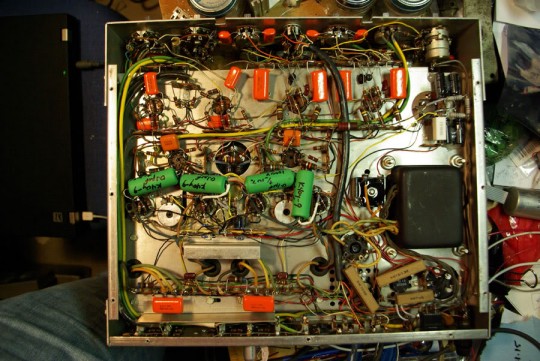
Can you see it? Let’s take a look at this schematic:
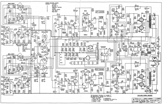
This is the Scott 299D schematic, and comparing it to the 222C schematic, we can play a game of spot the difference…
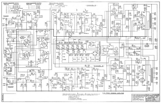
Because these are both push-pull amps, the output tubes need to have matching cathode current consumption specs, within reason, as one tube is responsible for the ‘push’ and the other for the ‘pull’ (think AC sine waves, with the positive and negative swings about the ground reference).
The differences we’re looking at specifically between these two schematics pertain to how each amp biases the output tubes; the 222C has a basic scheme where each pair of tubes can have some small difference in cathode current because this difference can be ‘balanced’ out using the ‘BAL’ pot. This BAL pot splits the bias supply between the tubes until both are drawing the same current. However the quad will need to be ‘matched’ to ensure that the left and right channel will draw the same amount of current, and sound the same.
The 299D uses a similar layout, naming the BAL pots as ‘DC BALANCE’ in this case, but adds an additional potentiometer to each channel, where with the 222C a quad of matched tubes might be required, the 299D really only requires two pairs of matched tubes. The added DC BIAS pots allow the operator to set the bias point per pair of tubes. This is beneficial because now not only can we employ inexpensive pairs of tubes, but we can set the operating point between channels to match, and even run the tubes cooler should an expended life be desired, or hotter to taste.
Neat! So, how do I retrofit this into my amp, and how can I adjust it in situ? I will need to add two accessible potentiometers and a set of tip-jacks to indirectly measure current with. Current will be measured using 10? resistors, with the tip jacks setup to measure voltage over them, and current will be a quick move of the decimal.
Some quick calculations and I found that for this mod I would require two 10k? pots and two 10k? resistors to elevate the pots from ground and achieve a variability from -10VDC up to -24VDC for the bias.
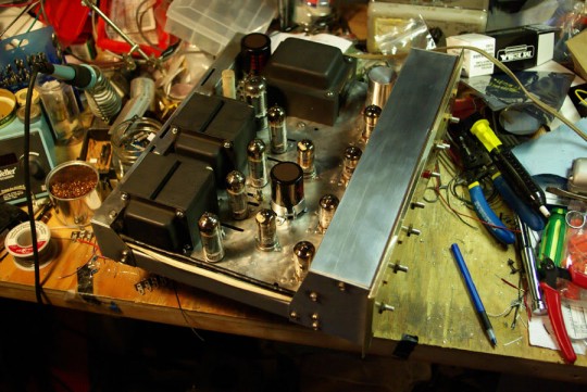
I initially added in the new potentiometers and the new resistors for testing my theory, with a layout as shown:
You can see the pot shafts sticking up from the vents between the pairs of output tubes:
When I verified operation and tuned in the adjustable range with additional resistors, I started my search for tip jacks. I scored some sweet NOS tip jacks on eBay:
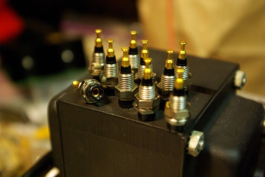
Gold plated, machined nuts, and a first grip on the probes. Better than I could have hoped for! Unfortunately I had to drill the top plate for these to be mounted. I decided on using five; one for a common ground and one for each tube. Looking back on this project, two jacks per tube would have been a better choice as I could then make my adjustments while watching all the currents at once, however this raises issues of calibration errors between meters (and that’s another bag of cats).
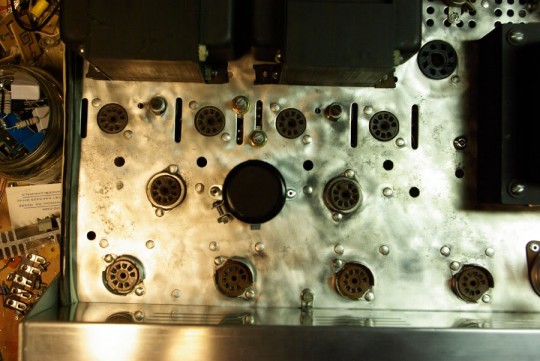
With the top plate drilled, the capacitors have to be moved around for everything to fit underneath. The tips jacks were installed and the amp was buttoned back up. I biased each of the tubes to a cool 23mA by measuring 0.23V at each of the test points (remember Ohm’s law, I = V/R, where R=10?) and sweet, sweet music was all that was left to make with this amp.
Unfortunately I don’t have any photos of the top side of this amp with everything done, but I hope this helps an ambitious builder sometime down the road!
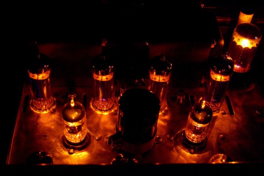
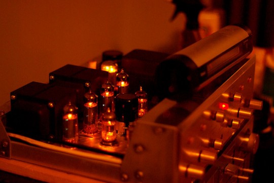
Here are some photos of the amp lit-up before the final bias hacks!
That wraps it up for this series.
Tear the covers off stuff you own, pull out the power tools, and remember: if it ain’t broke, you’re not trying.
P.