I have a 1GHz universal counter and a 5MHz function generator as well as an ancient RF generator, but I don’t really do a lot of super accurate frequency stuff to warrant a Rubidium standard (yet). In early 2012 I threw down an offer of $10 on a Bulova PCOXO-HP02 oscillator, and accepted the counteroffer of $12.50.

Now I needed to figure out how I could use the thing.
I know what an OCXO is (oven-controlled crystal oscillator) but a PCOXO I’d never heard of, and I assume it means precision controlled oven crystal oscillator (which has to be better, right?). A lot of searching on electronic timekeeping-related mailing lists uncovered that this oscillator was used by HP in their 8660C synthesized signal generators. Additionally I was able to find the pin-out for the electrical connections! Now we’re getting somewhere from this being a neat piece of curio to something useful.

For those of you that might stumble on this information, here’s the pinout that I found:
- Oscillator DC Voltage (5V~28V)
- Oven DC Voltage (20V~30V)
- 10.000MHz Output, Level of 0.9V DC (RG316 connector)
- Ground
- Unknown (Continuity with Ground)
- Unknown
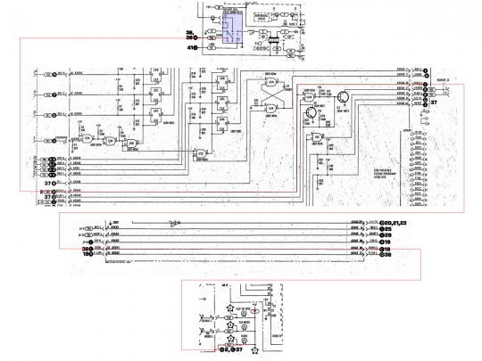
This is really useful, but that one ‘unknown’ terminal got me curious. I started to dig. I downloaded a copy of the HP 8660C’s service manual and began working back and forth through the pages of schematics to trace the signal and see where all the pins went. What I found is that HP operates the oven at either +30V or +35V DC (conflicting numbers on different pages), and that they supply the oscillator +20V DC. After all my back and forth, I decided to keep track of the information in Paint and see what I could compile for that #6 pin. This is the mosaic I assembled:
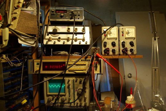
Pin six snakes through a series of boards and connects to the end of a lamp, whose opposite end is connected to a +5V source. Awesome! Pin 6 is an indication that the oven that achieved temperature! (I unfortunately never tested this functionality, but I assume based on other devices that the ‘oven’ lamp remains lit until the temperature is stable, implying that pin 6 is grounded while warming up, and then shows +5V when it’s reached the target temp) I bought an RG316 to BNC connector and was ready to test. Armed with two HP 721A power supplies (the first transistorized supply HP made, cute as a button, easy to fix, and usually inexpensive), my oscilloscope, a multimeter, and my universal counter, I set to work wiring everything up. I flipped the switches on my supplies and adjusted my counter–right from the get-go I was seeing a 10.00034MHz signal!
I found that the heater was a pig for current–a weak point of my supplies, as they’re only capable of supplying 0~30V to a maximum of 150mA! (notice the sag; I set 30V on the supply to the heater, and I’m reading 12.9V on the multimeter) What more could you need! Additionally the sine wave is excellent. I set my oscilloscope to 50ohms input impedance and couldn’t ask for a better picture.
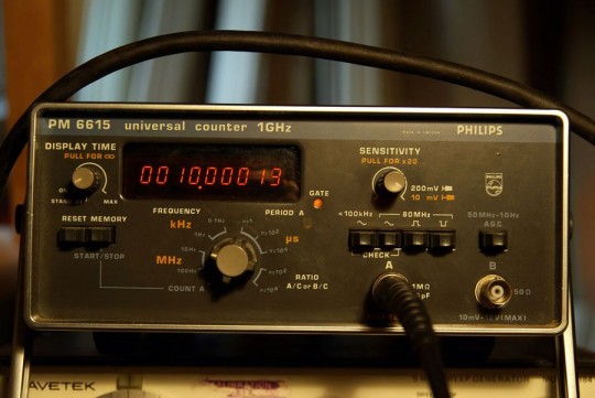
After 10 minutes of testing I got down to 10.00013MHz on my counter (which itself is probably out of calibration). I forgot to verify the functionality of the ‘oven’ pin. Right, onwards! The thing works and it needs a home. I have a BUD Industries aluminum enclosure I picked up at a HAM fest at some point and set to work my designs into that case. The plans were forged on the bus ride home one day, scribbling on a newspaper that I later transcribed onto a piece of scrap paper at home.
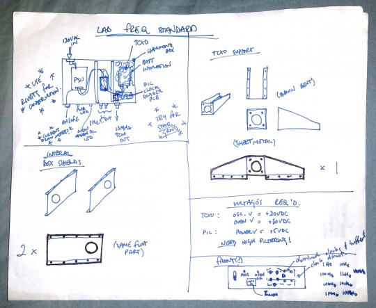
The chassis and internal elements are to be made from bent aluminum sheet or thin plate. There are to be three sections, inside the box: one will house the power supplies, one will be where the frequency divider lives (giving me multiple outputs), the last one will house the oscillator itself, and will be filled with batt insulation. Holes in the walls will allow wires to pass through and will also shield the sections from one another to help keep any potential RF noise inside the box down. With all that work done, my Thesis project picked up and I had to drop my extra-curricular activities. And as of writing this is as far as this project has made it. I vow to complete this project, however with work keeping me busy and my Dual-Mono Amplifier project taking up my workbench, I haven’t had the chance to return to this project.
5 Comments
Pingback: Oscillatori, andiamo ad iniziare! | Adelmo's World