A couple years back my then-girlfriend said ‘hey, you fix stereos–I want a stereo!’ And so a Christmas gift was born.
I found a Pioneer QA-800A quad amplifier with a bad channel and lots of DC offset as well as a matching tuner, a Pioneer TX-8100 with a few bulbs out. Both were sold as-is and that was fine with me! I picked them up from the post office and set to work.
The QA-800A was straight-forward enough: pull and test the output transistors, then work back, testing the driver transistors, and I found one of them had gone south. After reading, it wasn’t uncommon for this part to fail, so I replaced the same part in every channel with modern equivalents. The chassis was tweaked a bit and the wood case was cracked, so I used cabinet clamps to bring the chassis back into square and using wood glue I fixed the case up. I replaced the single lamps with LEDs, as well.
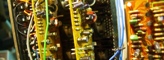
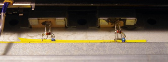
The tuner was also an easy thing to go through: I have hundreds of ‘warm white’ LEDs that I replace bulbs with as I come across them, and so that’s where I started. The bulbs are supplied with AC, so I had to use two LEDs wires backwards in parallel, with dropping resistors. Where I couldn’t squeeze in two LEDs, I harvested some diodes from an old CRT monitors and wired that in parallel with the LED to shunt the reverse current away. There were a lot of bulbs, and this step took a while, but I got it done.
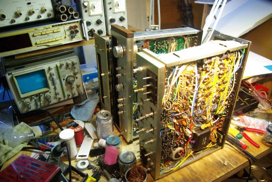
Now, when I first got the tuner, it worked fine, tuning in stations well and working very well. I replaced the capacitors with whatever I had on hand and wrapped it back up only to find that the stereo indicator stopped working. I checked the voltage over the indicator: my multimeter showed 10mV when off of a station, then jump to 500mV and settle back down to 10mV when on top of a strong station. I tried putting the bulb back into the circuit and I didn’t have any bulbs to replace this one with in the even it had burnt out. I tried listening through headphones and couldn’t really decide. Ultimately I hooked up the tuner to my oscilloscope to look at the Lissajous figure of the audio output.
Looking at the scope I tuned from zero signal strength, to full strength, and beyond. Flowery image? Stereo working, confirmed.
So, what the what?
Fiddling with the knob while the tuner is in bits means there’s things moving while I’m trying to probe, and it means I have one less hand free to take measurements. I rigged up my RF signal generator as an FM source and inductively coupled the antenna input to the RF gen’s output so at a flip of a switch I could get full signal.
Tracing the circuit out using a service manual I found on HiFi Engine I found the IC that was responsible for the alighting the stereo indicator.
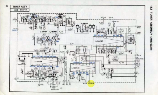
Squinting and looking over this document and I found (encircled in yellow) the ‘INDICATOR’ connection, which controlled the stereo indicator. Probing over the IC I verified that when switching between stereo and mono, I can see what looks like a capacitor discharge each time I switch between modes. Checking this pin relative to GROUND however, and I found was that I measured 0.200VDC in stereo and 0VDC in mono. With this, I knew what I had to do.
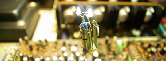
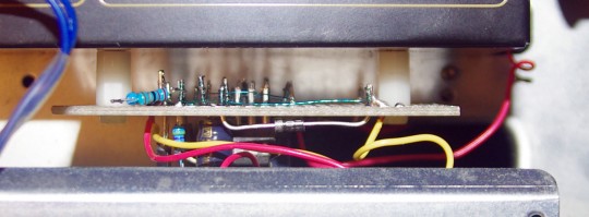
The chip was damaged, but I could still see a useful signal. 200mV is too little to drive an LED let alone a light bulb. I didn’t have any transistors on hand that would work in this case, so I went for gold by wiring an OPAMP, and with an approximate gain of 10, and used that to control a transistor that I had which would work. After testing that it did its job outside of the tuner, I then went and found some pick-off points where I could derive voltages (using an LM317) that the OPAMP wanted, and that the transistor + LED was happy with. I wire-wrapped + soldered it all together and…
Perfection.
I glued on a couple plastic mounts to the inside of the tuner to hold this new board I developed in place, and I had my tuning indicator back in business.
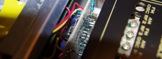
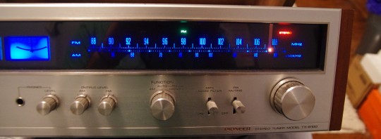
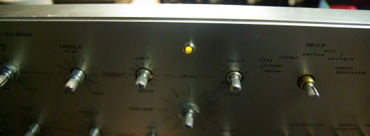
I’m sad I don’t have a schematic, I was making it up as I went along. It was a bit of a hack to get this working again, but in all a fun activity and the results worked out great. The purer white of the LEDs makes the dial a lot bluer (and my camera over-exaggerated it) in the best way possible, individual indicators included.
I hope this gives any other restorers out there a kick to get to get their old things up and running again!
3 Comments