This project really picked up steam in October 2012.
A couple years before this project came about, I built a box as the base for my second RH84 amplifier (design can be found here [opens in a new tab]) since my first build was based on the chassis of an unremarkable Claritone console amp (I assure you, no Project G stereos [opens in a new tab] were harmed in development of that project). The box was put together using red oak sourced from the clearance pile at Rona, cut on a not-quite-square compound mitre saw, and a table saw was used to rip the 6061 aluminum plate down to size. In the end the openings were not quite regular and I had to file the plates into fitment, but it turned out well.
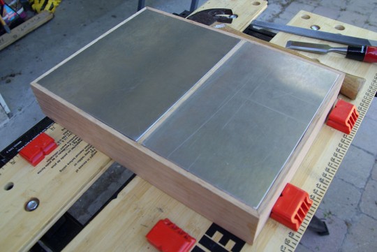
Right, so I’ve got the box.
On a forum that I’m a member of, another member posted a set of Akai M8 reel-to-reel pulls: the tube amplifiers, one true mono single-ended EL84 per channel–120V AC went into each amp, and each had its own speaker output. These amps are known for their sound, and many people purchase the pulls (or chop up the R2R machines themselves) and use the amplifiers as-is, however I wanted to go one better and try to rebuild the amplifier pair in a single chassis. There are two schools of thought with regards to the sound signature of an amplifier; some believe that the circuit is what drives the sound and others believe that it is the output devices–those output transformers which mate the high-voltage-low-current and high-impedance tube output circuit to low-voltage-high-current and low-impedance speaker connection. I bought a pair with no real thought or plan laid out in my mind, but based solely on their reputation and if anything to get ahold of those output transformers.
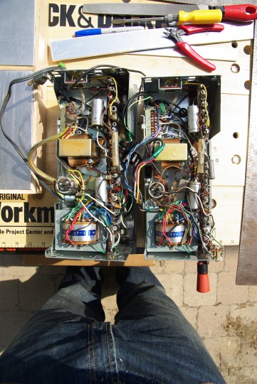
So, dang, there’s a lot going on inside these little boxes. And it’s all point-to-point. I started by looking at the schematic for the R2R (showing both channels) and tried to out the preamp section that was in place for reading the magnetic tape.
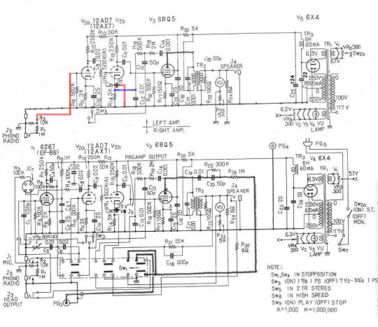
I didn’t want tone controls nor even a volume know–this was going to be a straight-up single-ended tube amp. I consulted with some tube gurus on my plan and was told that it might be better to start from scratch as this circuit uses both triodes in the 12AX7 bottle. The tube of choice is the 6EJ7, which is basically half of a 6DJ8, and a 6DJ8 lower-noise tube which is used as a common replacement for the 12AX7. All that’s happened here is that I’ve switched to a single triode tube with characteristics similar to the original tube.
I also decided at this time to make everything a nine-pin part, and switched from the 6X4 rectifier to the 6CA4 rectifier.
Ok! So, let’s see how this is all going to go together–time to disembowel the amps and see where all the big bits might go in the new box.
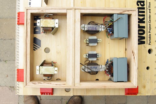
The keen observer will notice that there’s two too many chokes–the original M8 had a single 6H choke per channel, and at this stage I thought I had all the room in the world to add a second choke-filter stage in my supply section using a 9H choke. Still, this photo shows us that I should be able to comfortable get it all together into a single–and unbeknownst to me at the time–heavy box.
I found some GE motor-run paper-in-oil and Ducati (made in Italy!?) metalized polypropylene capacitors at Active Surplus. I bought a bag-full, hoping to match-up the parts with my LCR meter and try to balance each channel as much as possible. The plan in my mind at this point was to have the GE caps as the first stage after the rectifier, the 9H choke, a couple poly caps, the 6H choke, and a few more poly caps. The math was gorgeous–I could get a B+ of roughly 270V DC and 1.4mV ripple–however test-fitting these bits and I realized that it started to get cramped, quickly.
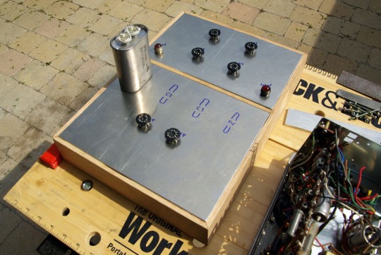
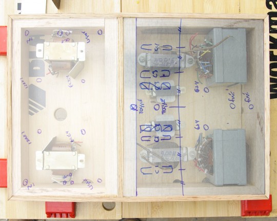
Things are already looking a bit tight. Where would my poly caps go? What about space to run wires around? I pressed on. I found some smaler PIO motor-run caps that could fit underneath, if I cut out the 6H choke, and I could achieve higher capacity by packing the top with the poly caps. The math worked out fine, leaving me with a theoretical B+ of 275V DC and roughly 48mV of ripple. Good enough. I started drilling, hacking, filing, and milling the plate into submission.
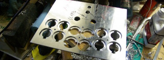
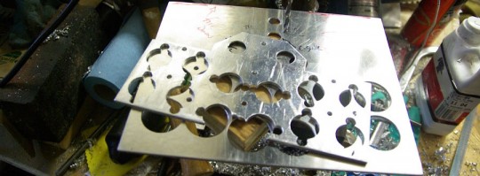
I designed the layout in CAD using Pro/ENGINEER Wildfire 4.0 first, setting the centre distances between all the capacitors to each other, manually dimensioning the distance from the edge of the plate, the locations of the fuse holders, and the locations of the rectifier tubes lay at the centre of a circle that’s driven by the location of the two capacitors nearest the tubes. Parametric design for-the-win.
The actual drilling of the plates involved drilling seven tooling holes, and which point the two plates were bolted together and the centres for each of the capacitor holes and tube socket holes were pilot-drilled. The plates were still bolted together when the holes for the tube sockets were made, and then the plates were separated out for machining. I had some tube sockets on hand which required clamping and I settled on using two-plates to sandwich the sockets between. The funny looking holes in the bottom plate will pick up on some molded plastic features on the bottom of the poly caps to retain them and maintain their orientation. When the holes were all made, excess material was cut away with a jigsaw on the lower plate for allowance of the power transformers.
I got some time on a milling machine and got the tube sockets fitting. This is how the whole sub-plate assembly works:
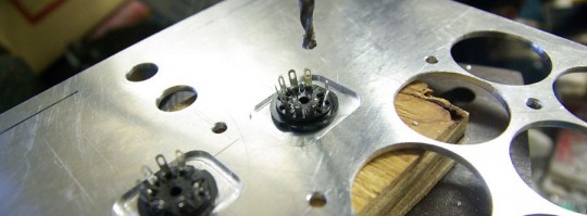
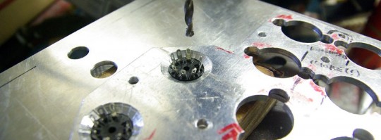
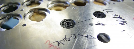
I did the same drill-and-mill process on the amplifier plate (photo taken before this procedure). A couple more holes here and there and I was ready to dry-fit everything:
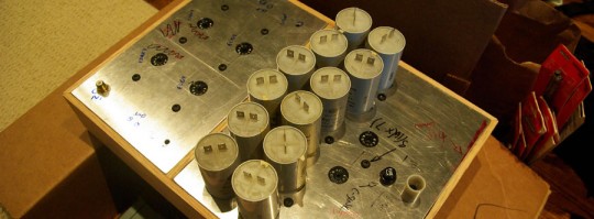
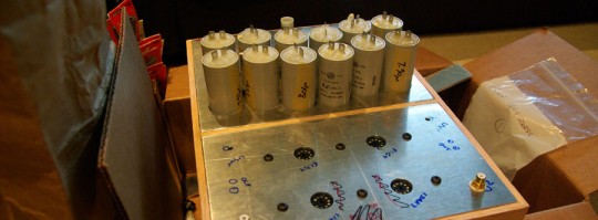
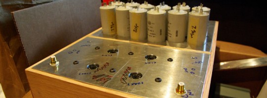
I love the clean aesthetics of a nice, hardened, button head cap screw.
That’s all for now and stay tuned for Part 2!
 About
About
2 Comments